
The ICAO Flight Plan
(Updated on 25th February 2021)
The Flight Plan
Correct use of the flight plan is essential for all pilots. In Ireland, flight plans can be filed by the following methods:
- Telephone
- Fax
- Electronically (IAA Website)
- In-flight
This post will primarily focus on how to complete the written version of the ICAO flight plan. Students are expected to know how to file a flight plan and must know how to complete the flight plan properly. Mistakes in the flight plan will lead to delays in the flight.
Any pilot flying into (or passing through) Irish Controlled Airspace will be required to file a flight plan at least 60 minutes in advance. If you are landing at an aerodrome that is notified as Prior Permission Required (PPR), you should note that the filing of a flight plan does not constitute prior permission. Flight Plans are required for the following:
- Any flight passing through Class A airspace
- Any flight passing through Class C airspace
- Any flight crossing an international Flight Information Region (FIR)
- When flying more than 3nm from the coast or over a mountainous or sparsely populated area
Although a flight plan is required for all flights within controlled airspace, you may file a flight plan for any flight (even if the flight is completely outside controlled airspace).
When completing a flight plan, the following rules apply:
- Use capital letters, one letter in each space of the field (unless field are not divided into spaces)
- Adhere to the prescribed formats and manner of specifying data
- Any data should be inserted only in the fields and spaces provided.
- Where excess space is available, leave unused spaces blank.
- All times should be clock times in 4 figures UTC (e.g., 1800, 0930, etc.). Do not use separators e.g. colons
- The term “aerodrome”, where used in the flight plan, is intended to cover also sites other than aerodromes, which may be used by certain types of aircraft, e.g., helicopters or balloons.
- Note that item numbers on the form are not consecutive (they correspond to item type in standard ATS messages).
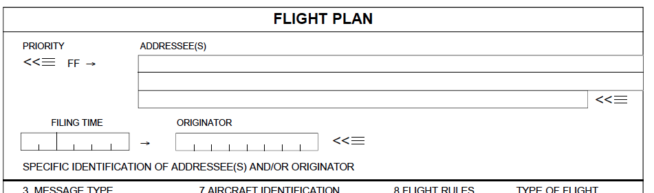
- Items preceding item 7 are to be completed by ATC and COM services
- Items 7 to 18 should be completed as indicated below.
- Item 19 completion is to facilitate alerting of SAR (Search and Rescue) services.
Contents of the Flight Plan
Item 7
AIRCRAFT IDENTIFICATION (maximum 7 characters)
This consists of the aircraft registration letters (or the company designator followed by the flight number) which are to be used by air traffic services for radiotelephony communication and coordination.
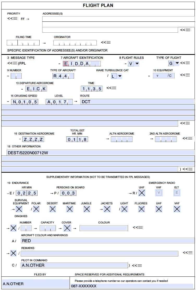
This field can be filled in by entering the registration of the aircraft (omit any hyphens). E.g. EI-DDA would be entered as EIDDA.
Item 8
FLIGHT RULES AND TYPE OF FLIGHT (2 characters)
This item indicates both flight rules and type of flight. Flight rules are important due to different regulations, weather and separation minimums for IFR and VFR flights.
Insert one of the following letters to denote the category of flight rules with which the pilot intends to comply. Options are:
- I for IFR
- V for VFR
- Y for IFR first, then VFR (this will indicate to ATS that during the flight a pilot will call for IFR flight cancellation)
- Z for VFR first, then IFR (this will indicate to ATS that during the flight a pilot will call for changing to IFR which will require ATC clearance from ATS)
If “Y” or “Z” is filed, specify, in the route section of the flight plan, the point(s) where a change in flight rules is planned. Similarly, where there is more than one change in the type of flight rules, the code to be used is to reflect the first rule, i.e., use “Z” for VFR/IFR/VFR.
Then insert one of the following letters to denote the type of flight if required by the appropriate ATS authority. Options are:
- S for scheduled air service
- N for non-scheduled air service
- G for general aviation
- M for military
- X for other than the preceding categories
The most common option for general aviation is: VG (assuming You will fly VFR general aviation flight)
Item 9
NUMBER AND TYPE OF AIRCRAFT AND WAKE TURBULENCE CATEGORY
Insert number of aircraft, if more than one (1 or 2 characters) followed by type of aircraft (2 to 4 characters).
The type of aircraft is indicated by the manufacturer’s designator. If no such designator has been assigned, or in the case of formation flights comprising more than one type, insert “ZZZZ” and specify the number(s) and type(s) of aircraft in Item 18 (see below) preceded by “TYP/” (up to 60 characters can be put, for example: TYP/3R44 2B206).
ICAO aircraft type designators are presented in ICAO Doc 8643.
The designator for the Robinson R44 is – R44
The designator for the Robinson R22 is – R22
Then add ICAO Wake Turbulence Category (1 character). Options are:
- /L – LIGHT, to indicate an aircraft type with a maximum certificated takeoff mass of 7000 kg (15 500 lbs) or less.
- /M – MEDIUM, to indicate an aircraft type with a maximum certificated takeoff mass of less than 136 000 kg (300 000 lbs), but more than 7 000 kg (15 500 lbs).
- /H – HEAVY, to indicate an aircraft type with a maximum certificated takeoff mass of 136000 kg (300 000 lbs) or more.
Item 10
EQUIPMENT
The COM/NAV/SSR equipment on board and its serviceability must be inserted by adding the appropriate suffixes. The first suffixes will denote the COM/NAV equipment, followed by an oblique stroke, and another suffix to denote the SSR equipment. Options for COM/NAV equipment are:
- N if no COM/NAV/approach aid equipment for the route to be flown is carried, or the equipment is unserviceable,
- or S if standard COM/NAV/approach aid equipment for the route to be flown is available and serviceable.
IMPORTANT: standard equipment is considered to be VHF RTF, VOR and ILS unless another combination is prescribed by aviation authority local regulations.
NOTE: many pilots use “S” even though they do not have all the elements of ‘standard’ present and certified (for example no ILS). THIS IS A SERIOUS MISTAKE. If you are in the habit of doing this, list all your equipment with the letters given below.
If none of the above options apply or the aircraft has more equipment than indicated by “S” insert one or more of the following letters to indicate the COM/NAV/approach aid equipment available and serviceable:
COM/NAV equipment (only the codes most often encountered by General Aviation codes are given; for the complete list, refer to ICAO documents):
- D – DME
- F – ADF
- G – GNSS (IMPORTANT: When using the letter “G” on an IFR flight plan, the GPS receiver must be approved in accordance with the requirements from aviation authority). If used a NAV/ element in field 18 should be used to indicate the type of GNSS system.
- H – HF RTF
- K – MLS
- L – ILS
- O – VOR
- U – UHF RTF
- V – VHF RTF
- Z – other equipment carried (IMPORTANT: if the letter “Z” is used, specify in Item 18 the other equipment carried, preceded by COM/ and/or NAV/, as appropriate.)
Surveillance (SSR) equipment
Here insert one or two of the following letters to describe the serviceable SSR equipment carried:
- N – None
- A – Transponder – Mode A (code only indication)
- C – Transponder – Mode A and Mode C (code and altitude indication)
- E – Mode S, including aircraft identification, pressure-altitude and extended squitter (ADS-B) capability
- H – Mode S, including aircraft identification, pressure-altitude and enhanced surveillance capability
- I – Mode S, including aircraft identification, but no pressure-altitude capability
- L – Mode S, including aircraft identification, pressure-altitude, extended squitter (ADS-B) and enhanced surveillance capability
- X – Transponder – Mode S without both aircraft identification and pressure altitude transmission
- P – Transponder – Mode S, including pressure altitude transmission, but no aircraft identification transmission
- S – Transponder – Mode S, including both pressure-altitude and aircraft identification transmission.
Other indicators are B1, B2, U1, U2, V1, V2, D1 and G1 but these are very unlikely to be used in general aviation.
Examples: Aircraft with VHF only and no transponder – insert V/N. Aircraft with VHF, VOR, ADF, ILS, DME, HF, Mode A and C transponder – insert SDH/C.
REMEMBER to add oblique stroke between COM/NAV equipment codes and SSR equipment code.
The most frequent option for general aviation is: S/C
Item 13
DEPARTURE AERODROME AND TIME
(1) Departure Aerodrome (maximum 4 characters)
On an ICAO flight plan, use four character location indicators.
- Example: EIWT, EICK, EIWF.
- ICAO aerodrome designators are presented in the Aeronautical Information Publication (AIP) or ICAO Doc 7910.
If no location indicator is specified, as is the case in private landing sites or many of the land VFR aerodromes, insert “ZZZZ” and specify the latitude and longitude in Item 18 preceded by “DEP/”.
- Example: DEP/…………… AIRPORT
If the name of the departure point is not listed in any aeronautical publication, to indicate it in Item 18 use:
- – degrees and minutes of latitude and longitude.
- Example: DEP/5023N02214E
- – bearing and distance to a navigation point or navigational aid.
- Example: DEP/ABC180017 (which means bearing 180 degrees and distance 17 NM from ABC aid)
(2) Departure Time (maximum 4 characters)
Indicate the hour and minutes in Co-ordinated Universal Time (UTC) your estimated off-block time. Do not use nonalphanumeric characters (+ . ; = , ) they will not be accepted or printed.
Example: 1132
Item 15
CRUISING SPEED, ALTITUDE/LEVEL AND ROUTE
This is the most complex item. It contains very important information from the point of view of ATS therefore a careful and correct filling of this field is required. Mistakes in this field may be an indirect reason for such hazardous occurences as airspace infringement.
In item 15 insert:
- a) the first cruising speed as described in (A) below,
- b) the first cruising level as described in (B) below, and
- c) the route description as described in (C) below.
(A) Cruising Speed (maximum 5 characters)
Insert the true airspeed for the first or the whole cruising portion of the flight, in terms of knots expressed as “N” followed by 4 figures
-
- Example: N0110 (which means 110 knots true airspeed)
General aviation example: N0115 (assuming that You will fly with speed 115 knots)
(B) Cruising Level (maximum 5 characters)
Insert the planned cruising level for the first or the whole portion of the route to be flown, in terms of:
- a) flight level, expressed as “F” followed by 3 figures or
- Example: F085 (which means flight level 085),
- b) altitude in hundreds of feet, expressed as “A” followed by 3 figures
- Example: A055 (which means 5500 feet altitude)
- c) only for VFR flights in uncontrolled airspace, the letters “VFR”.
General aviation example: A015 (assuming that You will fly at 1500 feet altitude)
(C) Route (including changes of speed, level and/or flight rules)
To fill in the “Route” field use points (1) to (3) below and after each element add a single space. IFR flights and flights following designated airways are not within the scope of this post and are not referenced here.
(1) Flights outside designated ATS Routes:
- Insert points normally not more than 30 minutes flying time or 370 km (200 NM) apart including each point at which a change of speed or level, a change of track, or a change of flight rules is planned or when required by the appropriate ATS authority(ies).
- Insert DCT between successive points unless both points are defined by geographical co-ordinates or by bearing and distance.
(2) Significant point (2 to 11 characters)
- (a) Degrees only (7 characters):
- Insert 2 figures describing latitude in degrees, followed by “N” (North) or “S” (South) then followed by 3 figures describing longitude in degrees, followed by “E” (East) or “W” (West). Make up the correct number of figures, where necessary, by insertion of zeros.
- Example:51N025E
- Insert 2 figures describing latitude in degrees, followed by “N” (North) or “S” (South) then followed by 3 figures describing longitude in degrees, followed by “E” (East) or “W” (West). Make up the correct number of figures, where necessary, by insertion of zeros.
- (b) Degrees and minutes (11 characters):
- Insert 4 figures describing latitude in degrees, and tens and units of minutes followed by “N” (North) or “S” (South), followed by 5 figures describing longitude in degrees and tens and units of minutes, followed by “E” (East) or “W” (West). Make up the correct number of figures, where necessary, by insertion of zeros.
- Example:5220N00705W
- Insert 4 figures describing latitude in degrees, and tens and units of minutes followed by “N” (North) or “S” (South), followed by 5 figures describing longitude in degrees and tens and units of minutes, followed by “E” (East) or “W” (West). Make up the correct number of figures, where necessary, by insertion of zeros.
- (c) Bearing and distance from a navaid or navigation point:
- Insert the identification of the navaid (normally a VOR) or the name of navigation point, in the form of 2 or 3 characters (navaid) up to 11 characters when name of the point is used, next the bearing from the navaid/point in the form of 3 figures giving degrees magnetic, next the distance from the navaid/point in the form of 3 figures expressing nautical miles. Make up the correct number of figures, where necessary, by insertion of zeroes.
-
-
- Example: a point 170° magnetic at a distance of 20 NM from VOR “KLY” should be expressed as KLY170020.
-
(3) Change of speed and level (maximum 21 characters)
- Insert the point at which a change of speed (more than 5% TAS) or a change of level is planned, expressed exactly as in (1), followed by an oblique stroke and both the cruising speed and the cruising level without a space between them, even when only one of these quantities will be changed.
- Examples:LN/N0284A045
-
- RUDKA/N0305F100
- 52N021W/K0260M080
- 4602N07805W/K0200F165
-
- Examples:LN/N0284A045
Item 16
DESTINATION AERODROME, TOTAL ESTIMATED ELAPSED TIME AND ALTERNATE AERODROME(S)
(a) Destination aerodrome and total estimated elapsed time (10 characters maximum)
- Insert the ICAO 4-letter location indicator of the destination aerodrome followed by the total estimated elapsed time of your flight (NOT the planned time of landing).
- Insert “ZZZZ” followed, without a space, by the total estimated elapsed time, and specify the aerodrome name in Item 18 (below).
If the name of the arrival point is not listed in any aeronautical publication, to indicate it in Item 18 use:
- – degrees and minutes of latitude and longitude.
- Example: ARR/5417N02005E
- – bearing and distance to a navigation point or navigational aid.
- Example: ARR/KLY320008 (which means bearing 320 degrees and distance 8 NM from KLY point)
(b) Alternate aerodrome(s) (4 characters – ICAO)
- Insert the ICAO 4-letter location indicator(s) of not more than two alternate aerodromes, separated by a space or, if no location indicator has been assigned to the alternate aerodrome, insert “ZZZZ” and specify in Item 18 the name of the aerodrome, preceded by ALTN/. Rules concerning indicating alternate aerodromes positions (if not listed by ICAO code) are the same as for DEP/ and ARR/ elements.
- NOTE: no alternate aerodrome is required in a VFR flight plan.
Item 18
OTHER INFORMATION
- This item is for all other additional, important or helpful informations (not all are presented here; only those mostly used by GA pilots).
(a) “DEP/” followed by the name of the departure airport or bearing and distance to navaid/navigation point closest to departure point or coordinates (if no designator is assigned and “ZZZZ” is inserted in item 13). Up to 50 characters may be used.
Example: DEP/……… AIRPORT
(b) “DEST/” followed by the name of the destination airport or bearing and distance to navaid/navigation point closest to destination point or coordinates (if no designator is assigned and “ZZZZ” is inserted in item 16). Up to 50 characters may be used.
-
- Example: DEST/……… AIRPORT
(c) “TYP/” followed by type(s) of aircraft, proceeded if necessary by number(s) of aircraft, if “ZZZZ” is inserted in Item 9
-
- Example: TYP/2 AS350. Up to 60 characters may be used.
(d) “REG/” followed by the registration markings of the aircraft, if different from the aircraft identification in Item 7.
-
- Example: REG/4XDKM. Up to 50 characters may be used.
(e) “ALTN/” followed by the name of alternate aerodrome(s) or bearing and distance to navaid/navigation point closest to alternate point, if “ZZZZ” is inserted in Item 16. Up to 100 characters may be used.
-
- Example: ALTN/……… AIRPORT
(f) “DLE/” followed by details related to delay enroute (for example for the need of flight training). A place in space should be described as in, for example, DEP/ item, either by navaid or bearing and distance from a significant point enroute, along with duration of the delay. Up to 11 characters followed by 4 digits may be used.
-
- Example 1: DLE/KLY0015 – delay over KLY navaid, duration 15 minutes
- Example 2: DLE/WTD2300200040 – delay at point 230 degrees and 20 NM from WTD NDB point, duration 40 minutes
(g) “COM/” followed by significant data related to communication equipment as required by the appropriate ATS authority. Up to 50 characters may be used.
-
- Example: COM/UHF only (which mean that pilot will be able to communicate on UHF only)
(h) “NAV/” followed by significant data related to navigation equipment as required by the appropriate ATS authority.
-
- Example: NAV/INS (which means that inertial system is available and cerified on board). Up to 50 characters may be used.
(i) “EET/” followed by significant waypoints or FIR boundary designators with accumulated estimated elapsed times from takeoff to such points, if required/prescribed by appropriate ATS authority.
-
- Example:EET/ABC0120 XYZ0200 (which means that point ABC will be passed 1 hour and 20 minutes after departure and point XYZ 2 hours after departure)
-
- EET/EINN0204 (which means that entering of Shannon FIR is planned 2 hours and 4 minutes after departure)
-
- Example:EET/ABC0120 XYZ0200 (which means that point ABC will be passed 1 hour and 20 minutes after departure and point XYZ 2 hours after departure)
(j) “STS/” followed by particular reason for special handling by ATS (hospital aircraft – STS/HOSP, one engine inoperative would be – STS/ONE ENG INOP, no radio – STS/NORDO)
-
- Example: STS/HAZ (which means hazardous cargo on board)
Other abbreviations include the following:
- – ALTRV – for flight with specified altitude reservation
- – FFR – for fire-fighting flights
- – HAZMAT – for flights with hazardous materials
Two abbrevaitions are no longer valid: “ATFMEXEMPTAPPROVED” and “EMER”
(k) “OPR/” followed by name of the operator, if not obvious from the aircraft identification in Item 7.
-
- Example: OPR/BIG COMPANY
(l) “DOF/” followed by the date of the flight in a six-figure format (if flight plan was filed on earlier date, maximum 120 hours before EOBT).
-
- Example: DOF/140613 (which indicated that the flight will take place on 13th of June 2014)
(m) “PER/” followed by performance of the aircraft according to ICAO document 8168 (categories “A”,”B”,”C”,”D”,”E” or “H” for helicopters).
-
- Example: PER/A
(n) “ORGN/” followed by contact details to flight plan originator. Up to 30 characters may be used.
(o) “RMK/” followed by any other, plain language, remarks when required by the appropriate ATS authority or deemed necessary. There is no limit in number of characters to be used.
-
- Example:RMK/TRAINING ILS APPROACH AT ………. AIRPORT
-
- RMK/STUDENT SOLO FLIGHT
-
- Example:RMK/TRAINING ILS APPROACH AT ………. AIRPORT
Item 19
SUPPLEMENTARY INFORMATION
- Here one can provide all information concerning safety and security of the flight as well as details helpful during search and rescue mission.
(a) “E/” and 4 figure group indicates the fuel endurance in hours and minutes.
-
- Example: E/0430
(b) “P/” allows insertion of the total number of people (passengers and crew) on board. If total number is not known during flight plan filling, insert “P/TBN” (to be notified). Use leading zeros if necessary to make three digits in this field.
-
- Example: P/005 NOT P/5 or P/050.
(c) at position “R/” (radio):
-
- – cross out indicator “U” if UHF on frequency 243.0 MHz is not available
- – cross out indicator “V” if VHF on frequency 121.5 MHz is not available
- – cross out indicator “E” if an emergency locator transmitter (ELT) is not available.
(d) at position “S/” (survival):
-
- – cross out all indicators if survival equipment is not carried
- – cross out indicator “P” if polar survival equipment is not carried
- – cross out indicator “D” if desert survival equipment is not carried
- – cross out indicator “M” if maritime survival equipment is not carried
- – cross out indicator “J” if jungle survival equipment is not carried.
(e) at position “J/” (jackets):
-
- – cross out all indicators if life jackets are not carried
- – cross out indicator “L” if life jackets are not equipped with lights
- – cross out indicator “F” if life jackets are not equipped with fluorescein
- – cross out indicator “U” or “V” or both (as in “R/” above) to indicate radio capability of jackets, if any.
(f) at position “D/” (dinghies):
-
- – cross out indicators “D” and “C” if no dinghies are carried or
- – insert:
- (NUMBER) – number of dinghies carried (example: 02) and
- (CAPACITY) – total capacity, in persons, of all dinghies carried (example: 006) and
- (COVER) – cross out indicator C if dinghies are not covered and
- (COLOUR) – insert colour of dinghies if carried.
(g) at position “A/” (aircraft) insert colour of aircraft and significant markings.
(h) at position “N/” (remarks) :
-
- – cross out indicator “N” if no remarks or
- – indicate any other survival equipment carried and any other remarks regarding survival equipment.
(i) at position “C/” (pilot) insert name of pilot-in-command.
Sample Flight Plan
Did you enjoy this post? Why not leave a comment below and continue the conversation, or subscribe to my feed and get articles like this delivered automatically to your feed reader.


Comments
No comments yet.
Sorry, the comment form is closed at this time.